Results 41 to 50 of 211
Thread: Spitfire IX Project
-
02-16-2009, 02:31 AM #41Boeing Skunk Works
Remember...140, 250, and REALLY FAST!
We don't need no stinkin' ETOPS!

Powered by FS9 & BOEING
-
03-01-2009, 11:18 PM #42
Well, a long weekend here and despite losing one day to work, the tools took a hammering!
It was good to finally get the fuselage off the paper and onto some wood. The plans needed a fair bit of “managing” as they came in a single sheet of paper. That meant that the various sized frames had to be traced out and from the plan after it had been cut up, making some bits harder (having to join plan bits together). Someone more organised may have worked backwards from the biggest bits to the smallest, hacking off sections as he went……I didn’t. Two reasons, really. First, hey, I’m just not that organised. Second well, er..see point one……


The seat frame, the frame behind the instrument panel and the plan. The seat frame was extended at the bottom to be square as it is the rear frame of the sim. This forms the “feet” and is rationalised away by the fact that there is a wing at the bottom anyway. The IP frame is the correct curve at the bottom. I will probably build a “wing stub” on the left side (for mounting the sim) and leave the right side with the curved base.

The seat frame is, at the moment cut fully rounded…this was going to be the frame at the back of the radio compartment but that made the sim too long. So now that top area will be cut down to the right shape and the angle aluminium frame above will form the canopy frame above the seat back. I actually formed it around the top of the seat frame with a rubber mallet, so it is nice and smooth and even.
I just need to cut a pattern (or Tracey will) for a curved aluminium plate to rivet onto the side which needed to be cut to allow the angle alu to bend.


How not to draw a pattern on to wood, measure twice, cut once…but probably best to remove the markings of the first (unsuccessful) measurement. …the firewall (front frame of the sim) also with “feet”. The spars on the side are the “main” spars which run the length of the sim, through the bottom of the instrument panel line. There are two more which will run either side about 8 inches from ground level.
The Instrument panel full mock up is next to be made because this will determine the placement of the main spars (which are not on the plan I bought) as they pass through a small “notch” cut in the bottom edge of the panel.

Cardboard pattern cut by my wife to be used for mapping out the short frames that make up the cockpit area and door. There are now two of these which will be cut up into the smaller sections that brace the actual cockpit seating area and mount most of the equipment.

All of the pieces from this weekend. (the silver objects are the bracing plates..I have to make the cockpit in two halves to fit through my doors.
A couple of detail shots to finish…the start of my IFF switch and destruction buttons unit and my brand new shiny fire engine red boost gauge. The flash made the metallic paint look blotchy and pockmarked. It is actually silky smooth after spraying a priming coat and four red coats over the already painted aluminium bezel but looks “bulky” like the original bakelite bezel was.


All in all a satisfying weekend’s work and proof for the wife that I don’t just spend money on parts!
."Tony"
In memory of Flt Lt Tony Hill who, on 5 December 1941, at the request of Doctor R V Jones, successfully photographed a small "Würzburg radar" at Bruneval on the French coast. This from a height of only 200 ft, at high speed, under fire and from a camera mounted obliquely behind the cockpit.
-
03-01-2009, 11:24 PM #43
Looks great Tony! Always good when you can save some money on the project.
I can't wait to see this after it all comes together. Boeing Skunk Works
Remember...140, 250, and REALLY FAST!
We don't need no stinkin' ETOPS!

Powered by FS9 & BOEING
-
Post Thanks / Like - 1 Thanks, 0 Likes, 0 Dislikes
 Tony Hill thanked for this post
-
03-01-2009, 11:33 PM #44
Looks real good Tony.
-
Post Thanks / Like - 1 Thanks, 0 Likes, 0 Dislikes
 Tony Hill thanked for this post
-
03-01-2009, 11:46 PM #45
Thanks Guys! The real work starts now I guess.
I also got news from Gwyn that the rudder pedals are done but I'll leave him to post pictures of them..they are STUNNING!!
regards
Darryl
."Tony"
In memory of Flt Lt Tony Hill who, on 5 December 1941, at the request of Doctor R V Jones, successfully photographed a small "Würzburg radar" at Bruneval on the French coast. This from a height of only 200 ft, at high speed, under fire and from a camera mounted obliquely behind the cockpit.
-
03-02-2009, 04:45 AM #46

737NG using Prosim737, Immersive Calibration Pro, Aerosim Solutions motorized TQ & cockpit hardware, CP Flight MCP & FDS SYS1X, SYS2X & SYS4X, FDS PRO FMCs, AFDS units & Glarewings, Matrix Orbital ELEC display, Pokeys Landing & Cruise alt display, Buttkicker Gamers, 3 x BenqMW811ST projectors with a Matrox Th2Go
http://www.aerosimsolutions.com.au
Supporter of MyCockpit.org, please join me in donating!!!
-
Post Thanks / Like - 1 Thanks, 0 Likes, 0 Dislikes
 Tony Hill thanked for this post
-
03-02-2009, 08:48 PM #47
Gwyn, marvellous work. I am constantly in awe of what you are building for me.
I send pictures and they turn into reality.
To show everyone how good this really is, here is a photo of the real thing…..

I told you the man was a maniac!!!
Inspired by Gwyn, I couldn’t leave the pit alone last night after work. When you are on a roll, I guess it is better to keep going. I decided to ditch the wood IFF Destruction and Control Unit and build it from aluminium instead. This required a few extra things…firstly I had to draw a pattern (unheard of) secondly I had to cut metal (NOT my thing) thirdly I had to fold and file it (bloody impossible for me) lastly, I had to get over my pathological fear of working with metal, drilled into me by a sad old man who liked nothing better than to crush young boys in his class.
Here are the results, with which I am pleased enough. Just do me a favour and don’t compare them to Gwyn’s work above!


It is now all primed and ready to be painted that sickly cockpit green colour that I will have to have the local paint supplier mix specially for me.
Baby steps…..
Darryl
."Tony"
In memory of Flt Lt Tony Hill who, on 5 December 1941, at the request of Doctor R V Jones, successfully photographed a small "Würzburg radar" at Bruneval on the French coast. This from a height of only 200 ft, at high speed, under fire and from a camera mounted obliquely behind the cockpit.
-
03-02-2009, 08:55 PM #48
Man that look absolutely great Tony!
The rudder pedals by Gwyn are awesome too. He IS the Master of Mechanics.Boeing Skunk Works
Remember...140, 250, and REALLY FAST!
We don't need no stinkin' ETOPS!

Powered by FS9 & BOEING
-
03-03-2009, 04:56 PM #49
Michael,
Cheers for that. It really did take a fair bit for me to pick up a hacksaw...but the next piece, the "spare globe holder" will be easier to build but have three cutouts. I will have to improve on those, as they will need to be perfectly round to fit the light holders.
Using aluminium will significantly improve the realism of the sim though, so.....
thanks
Darryl
."Tony"
In memory of Flt Lt Tony Hill who, on 5 December 1941, at the request of Doctor R V Jones, successfully photographed a small "Würzburg radar" at Bruneval on the French coast. This from a height of only 200 ft, at high speed, under fire and from a camera mounted obliquely behind the cockpit.
-
03-18-2009, 01:17 AM #50
More progress...
Hi all,
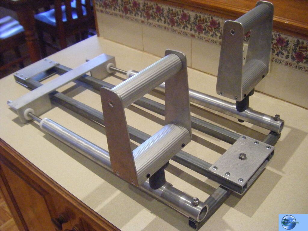
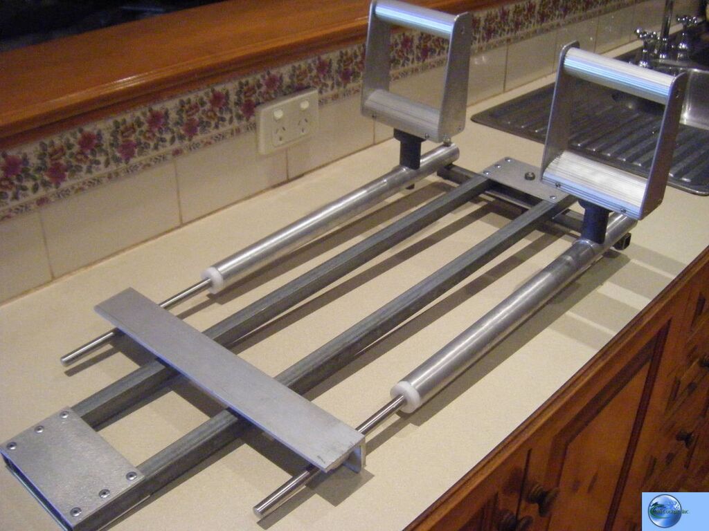
Here are some more progress shots of Darryl's plug'n'play flight controls. I plugged them in the other night for a 10 minute test flight and found that the ailerons were reversed...doh! So after a quick modification to the roll potentiometer mount it was ready to fire up the Merlin again. The Sidewinder software made it so easy set up and I've been flying "Darryl's Spitfire" every night since the controls have been working. It's been so long since I've flown anything but the 737 it has been great fun, the helicopters were great with this set up to. Another job that I won't want to hand over!
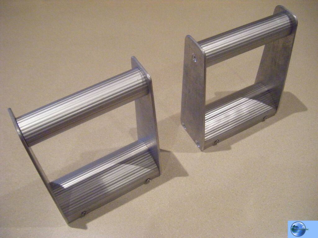
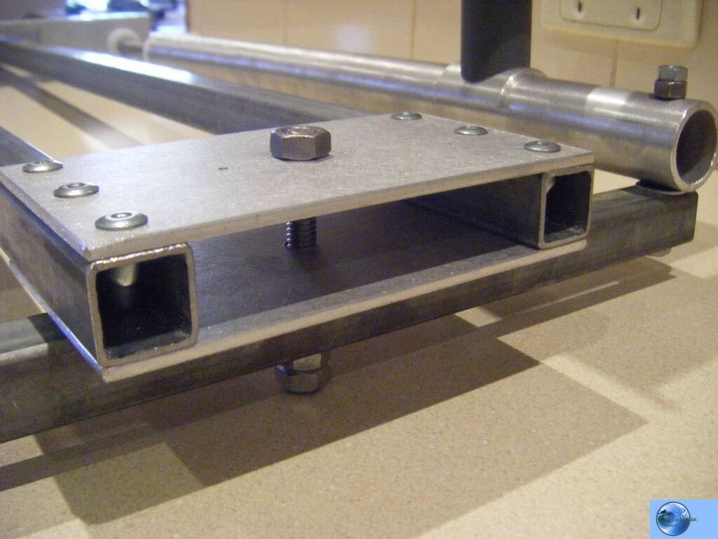
Front damper and rudder bar pivot point. (The timber is a temporary footing)
Brake switches and yaw pot drive
Pitch pot drive and adjustable yoke travel stops
Roll pot drive and the 'black box' which houses the Sidewinder joystick circuit boards.
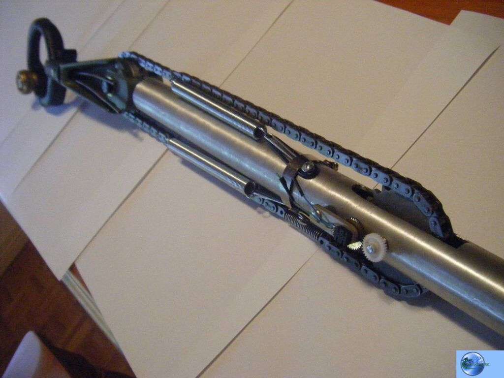
Door closers used for centering, they work much better than I expected which was very pleasing. Note the grey stoppers locked to the rods which keep the column in the neutral position. When the column tilts, the damper rod that isn't being pulled slides freely through the stainless brackets fixed to the column.
This is an airworthy replica spade grip supplied by Darryl, it is really heavy and the chain had to have large springs fitted for self centering.
Almost finished, it just needs the brakes and chain guard finishing before Darryl's paint job ruins the shine!
GwynLast edited by Westozy; 03-18-2009 at 01:37 AM.

737NG using Prosim737, Immersive Calibration Pro, Aerosim Solutions motorized TQ & cockpit hardware, CP Flight MCP & FDS SYS1X, SYS2X & SYS4X, FDS PRO FMCs, AFDS units & Glarewings, Matrix Orbital ELEC display, Pokeys Landing & Cruise alt display, Buttkicker Gamers, 3 x BenqMW811ST projectors with a Matrox Th2Go
http://www.aerosimsolutions.com.au
Supporter of MyCockpit.org, please join me in donating!!!
-
Post Thanks / Like - 1 Thanks, 0 Likes, 0 Dislikes
 Tony Hill thanked for this post
Similar Threads
-
Spitfire IX circa 1943
By graemesmith in forum Welcome to MyCockpit New here? Introduce Yourself!Replies: 2Last Post: 05-30-2010, 07:26 AM


 Reply With Quote



Prettys Womans from your town for night
HDG preselect function